
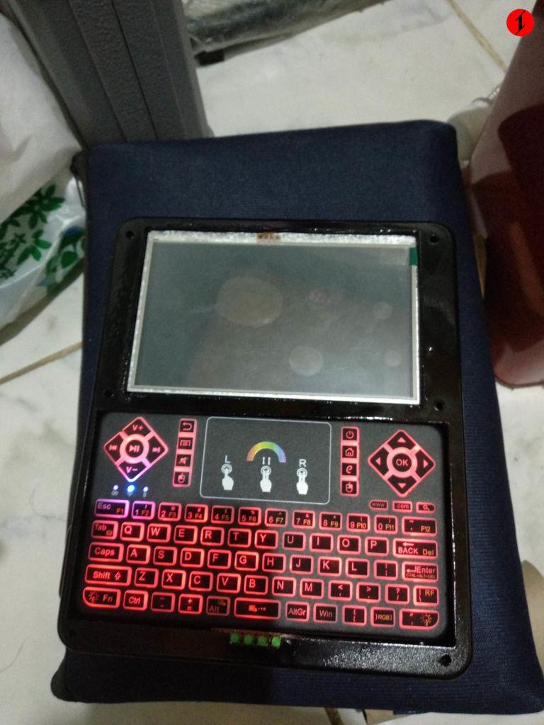
Too bad that the LCD module of this build is dead, I made an HDMI cable to see if it fixes the problem, it did not. This build can still be fixed though by buying a new LCD module for it.
The HDMI cable that I originally used is made out of this. I think I damaged the flex cable by bending it too much which it turn damaged the LCD module. I think I read or got an information from somewhere that if there is no HDMI signal to this LCD module if it is powered on, there is a possibility that it will be destroyed. I think that’s it, not sure.
It is my first time to build a complete Raspberry Pi or an SBC portable, this can still be refined. I showcased this project at the Manila Mini Maker Faire 2018.

The image above is basically the circuit of the whole build. The battery that I utilized is from a Xiaomi powerbank. It will automatically power on if it detects a load. You can see from the image that I put a switch there in series that goes in the power input of Raspberry Pi. There are test points below the Raspberry Pi board which you can take advantage of to solder stuff there.
Making the case, for me, is the trickiest part. I did not make use of 3d printing, or some CNC machine. But aren’t 3d printers CNC machines anyway? I think 3d printing is colloquially used if the process is additive, and CNC machines if it is subtractive.
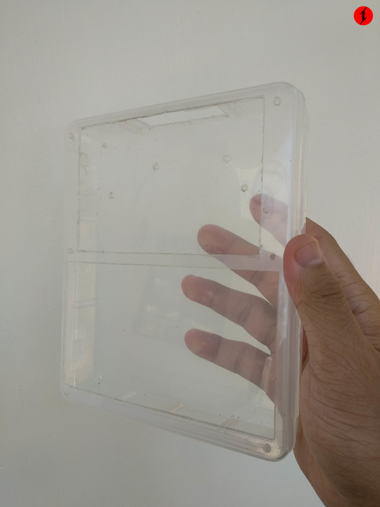
I made use of an off the shelf plasticware for the casing of my build. I got it from Japan Home Centre. I made a pattern around it so that I have a guide for cutting what needs to be cut. I used Inkscape to create this.

Errol helped me cut the plastic. I am not that confident that I will cut it fine.

The pattern is taped onto the plastic. As you can probably conclude, the small rectangle on the top is for the LCD. And the other rectangle is for the keyboard with touchpad. The circles are for screws for the case.

The plastic is now cut for the main parts. You can see the cutout for the Raspberry Pi USB and Ethernet port at the upper corner. The location of the switch is not yet located at the picture above, but it goes on the left side of the cutout of the ports.
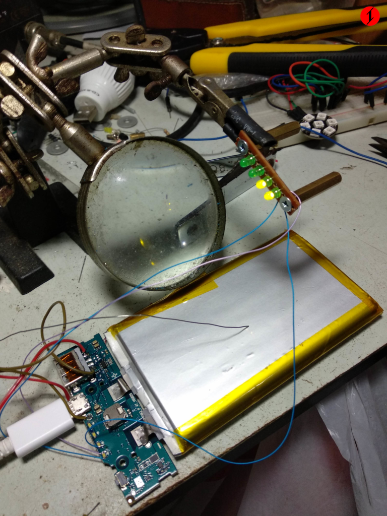
The powerbank has 4 LEDs indicating how much charge is left. I break it out, and it will be attached on the front side of the case.
The cutout for the LEDs on the bottom is not that right. I used a file to sand it off.
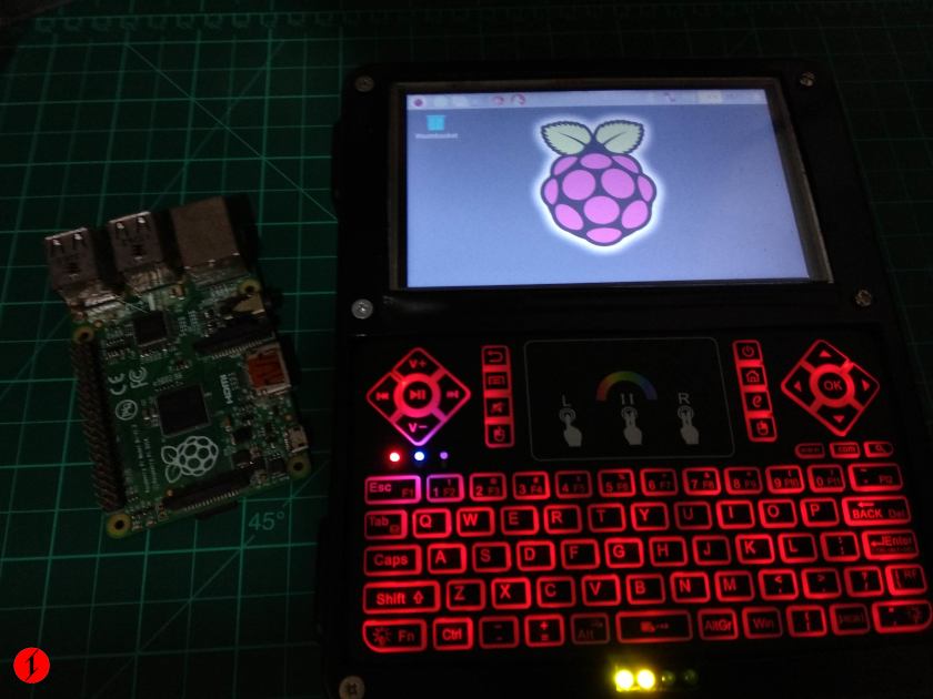
I used a Raspberry Pi 3 Model B in this build. I underclocked it to give room for the powerbank. The one located on the left on the featured image is a Raspberry Pi 1 Model B+ for scale.
Some specification of this build:
- Raspberry Pi 3 Model B
- 5inch touchscreen
- Full qwerty keyboard with touchpad
- 3.7v 10000mAh battery
- 4x USB ports(1 taken by keyboard)
- Ethernet port, WiFi, Bluetooth
The touch data of the screen is communicated to the Raspberry Pi via SPI.
The media keys on the keyboard is arranged in a way that resembles a game controller. You can remap it if you want to use some game console emulators.
There are really limitations if the case or the base of the case you will use is not really tailored to the project you are going to make. I hope I can get a 3d printer some time this year, hopefully. It will definitely be of help. I am currently eyeing at the Creality Ender 3.
There are also limitations from off the shelf electronics. It would be nice if some of these will be specifically tailored to a build.
If I am going to have a take again at an SBC portable, I hope that it would be better. Also I will probably include a speaker, and/or a 3.5mm jack.