
Buy: Shopee, Etsy
Code Examples: Github
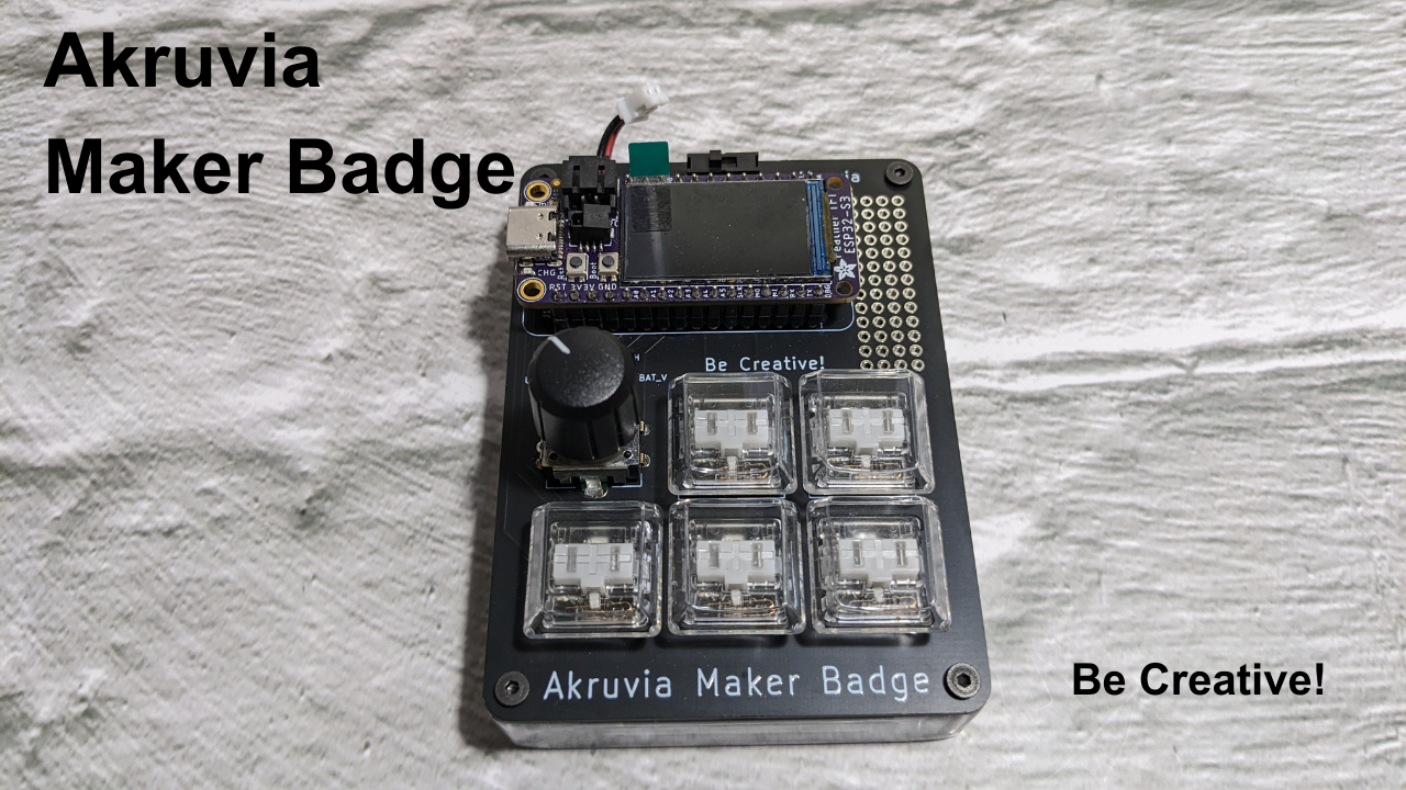
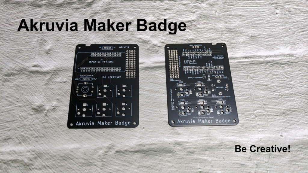
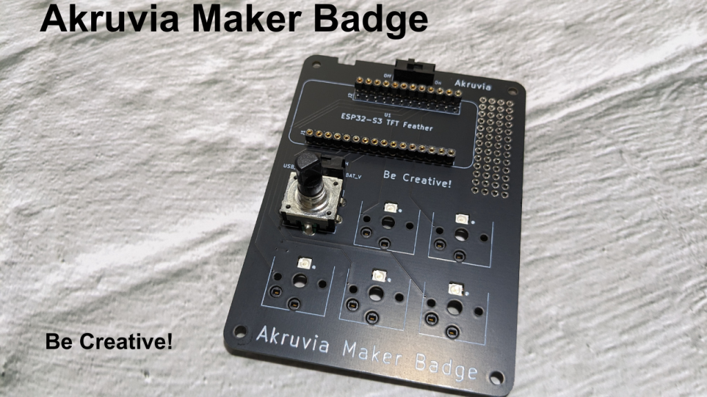
Akruvia Maker Badge
Want to assemble your own maker badge? Want to turn it into a macropad? Wi-Fi Scanner? BLE scanner?
Want to display your name for conferences/meetups? Want to make a game?
Be Creative!
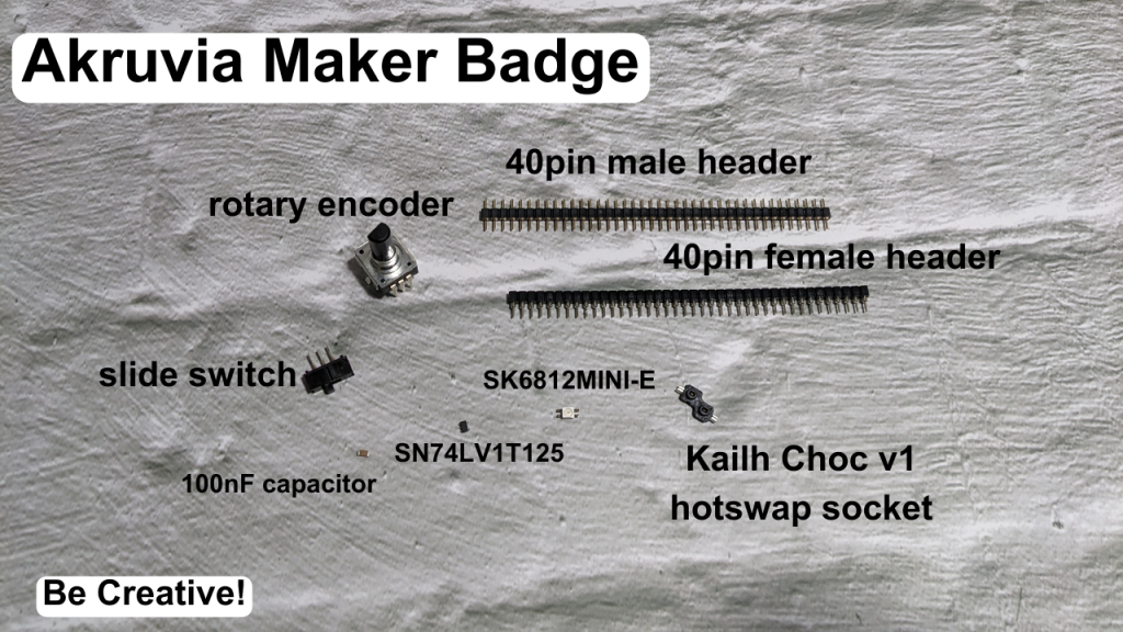
Product inclusions:
1x Akruvia Maker Badge PCB
1x SN74LV1T125
1x 1206 100nF capacitor
5x SK6812 RGB LED
5x Kailh Choc(version 1) Hot Swap socket
1x 40pin male header
1x 40pin female header
2x slide switch
1x encoder
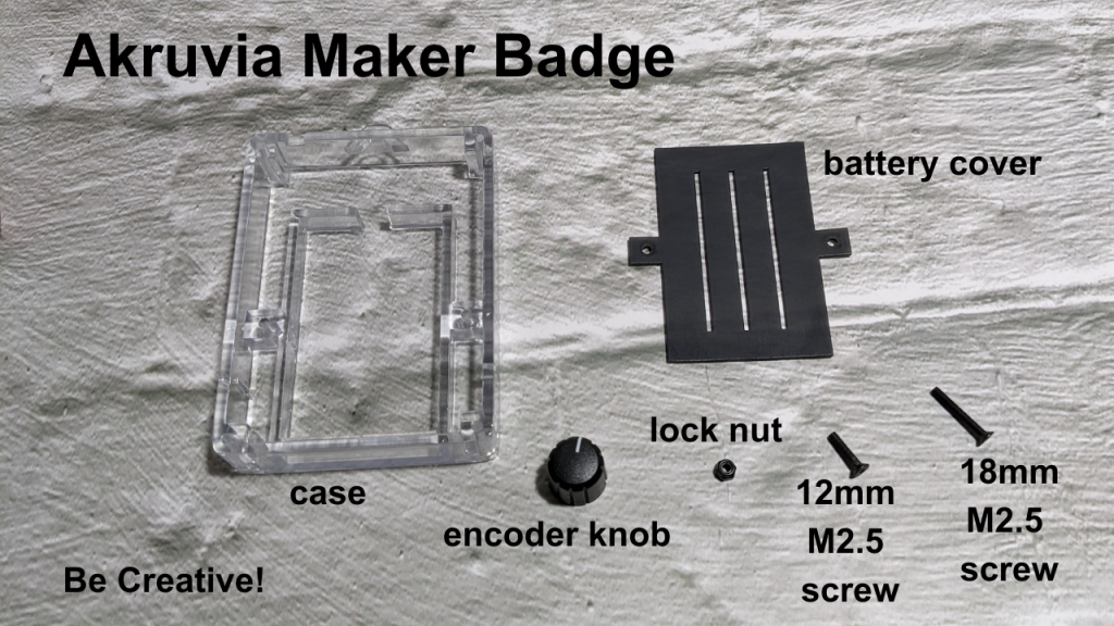
1x encoder knob
4x 18mm M2.5 screws
2x 12mm M2.5 screws
6x M2.5 lock nuts
1x transparent case
1x battery cover
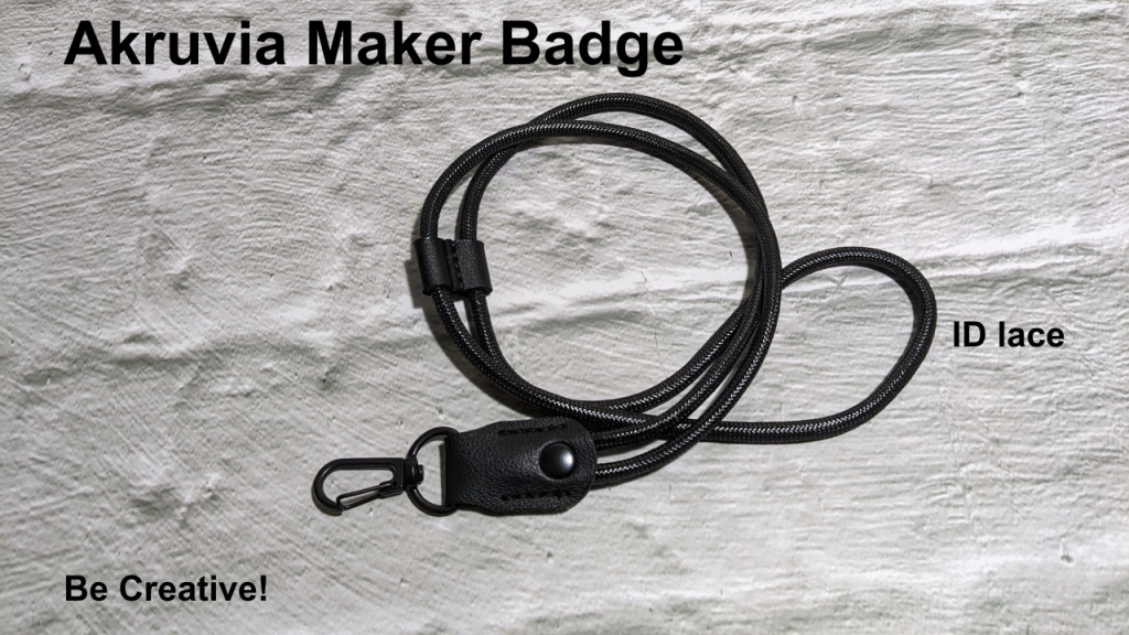
1x ID lace
Required:
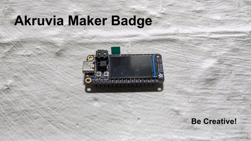
1x ESP32-S3 TFT Feather (with unsoldered pins)
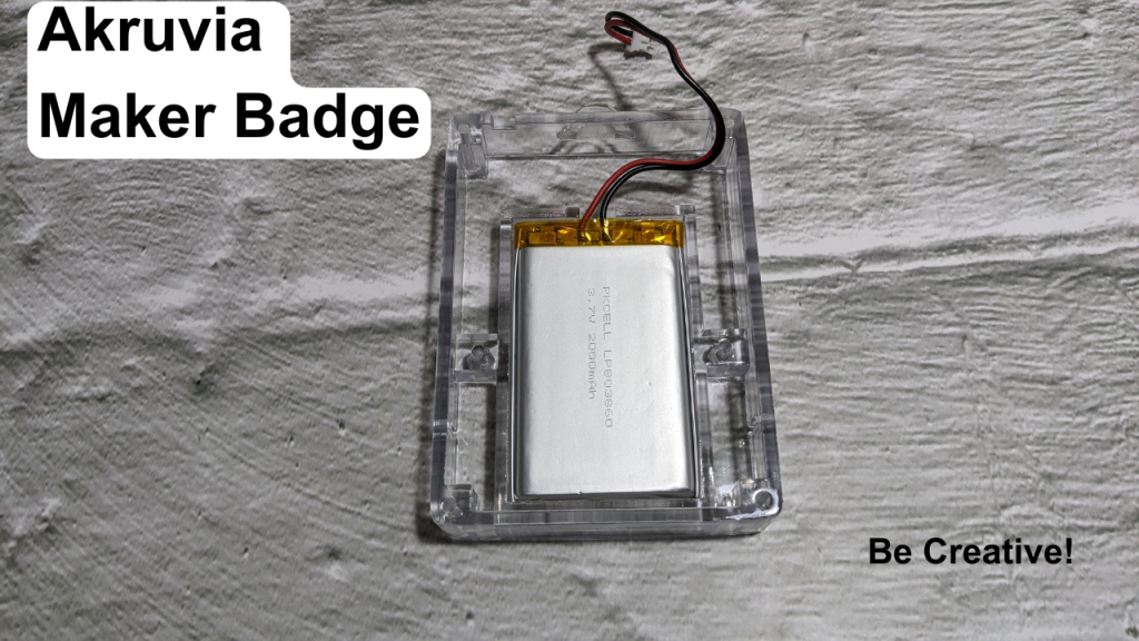
1x PKCELL LP803860 3.7V 2000mAh
5x Kailh Choc v1 switches
5x Kailh Choc v1 keycaps
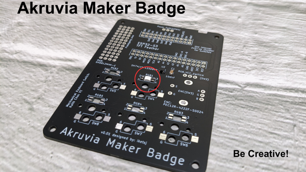
Akruvia Maker Badge PCB:
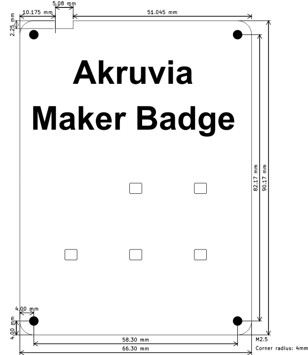
Akruvia Maker Badge Dimensions:
Soldering steps:
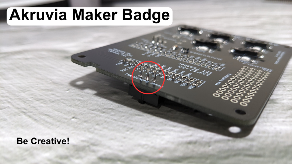
Step 1: Solder male header pins to ESP32 TFT Feather
Step 2: SN74LV1T125

Step 3: 100nF capacitor
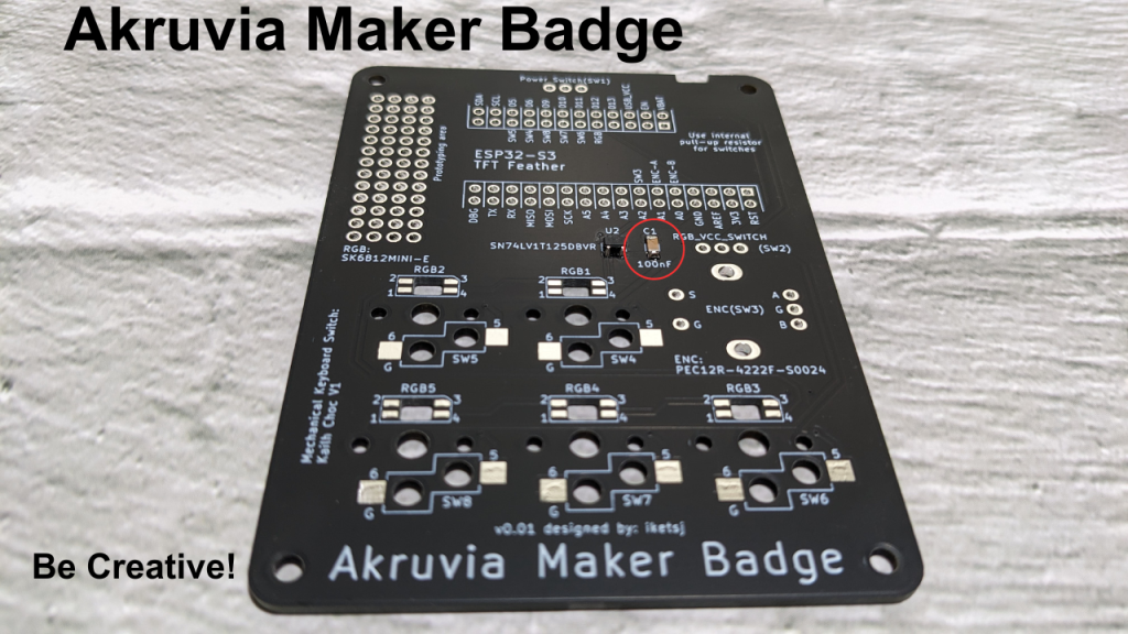
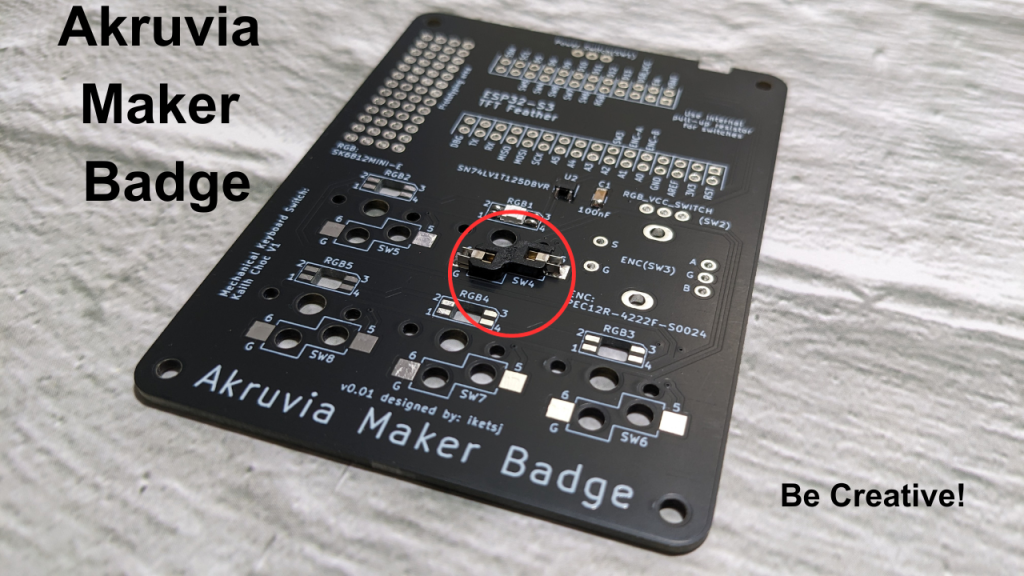
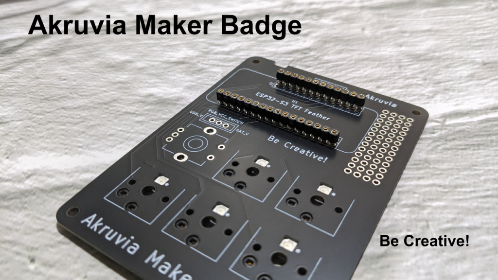
Step 4: RGB LEDs (RGB1-RGB5)
Step 5: Kailh Choc v1 hot swap sockets (SW4-SW8)
Step 6: female Header pins for ESP32 TFT Feather
Step 7: slide switches (SW1-SW2)

Step 8: encoder
Case assembly:
Step 1: Put the battery.
Step 2: Use the 2x 12mm M2.5 screws and 2x M2.5 lock nuts.
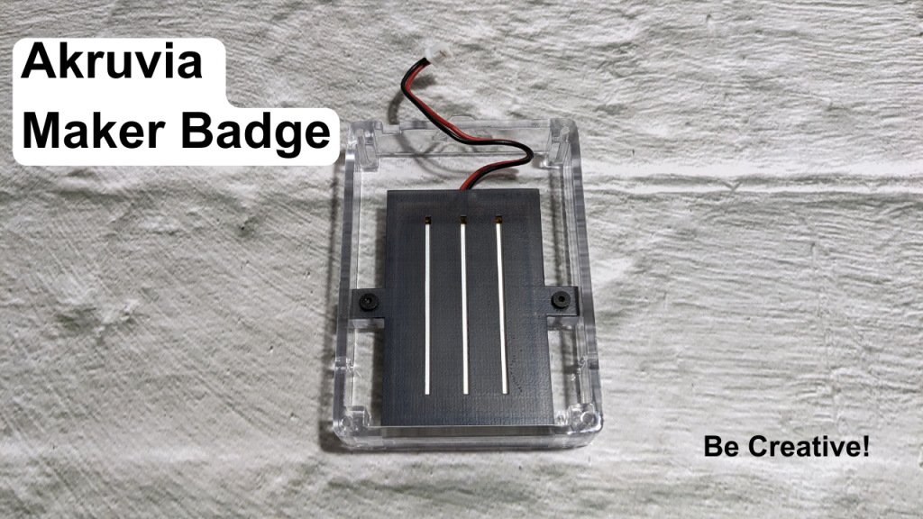
Step 3: Use the 4x 18mm M2.5 screws and 4x M2.5 lock nuts to attach the PCB to the case.

Pinout:
A0 – Encoder B
A1 – Encoder A
A2 – Encoder SW / SW3 (Enable internal pullup resistor)
D6 – SW4 (Enable internal pullup resistor)
D5 – SW5 (Enable internal pullup resistor)
D11 – SW6 (Enable internal pullup resistor)
D10 – SW7 (Enable internal pullup resistor)
D9 – SW8 (Enable internal pullup resistor)
D12 – SK6812 RGB LEDs (RGB1 to RGB5) through SN74LV1T125
Adafruit ESP32-S3 TFT Feather:
https://learn.adafruit.com/adafruit-esp32-s3-tft-feather/overview
Notes:
SW2 is the power selection for the RGB LEDs, get power from USB or Battery.
Relevant Links:
https://circuitpython.org/board/adafruit_feather_esp32s3_tft/
https://learn.adafruit.com/circuitpython-essentials/circuitpython-essentials
https://github.com/todbot/circuitpython-tricks