
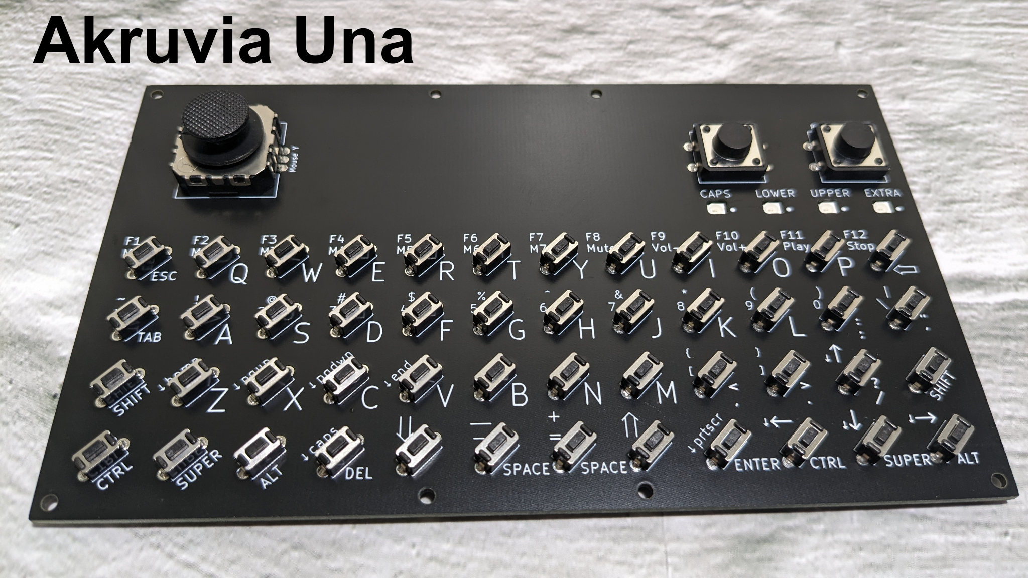
Akruvia Una
An unsoldered RP2040 USB Handheld Wired 12×4 Keyboard with a Mouse Pointer kit for your DIY Cyderdecks, UMPCs, handheld PC builds.
Be creative!
Product inclusions:
1x Akruvia Una PCB
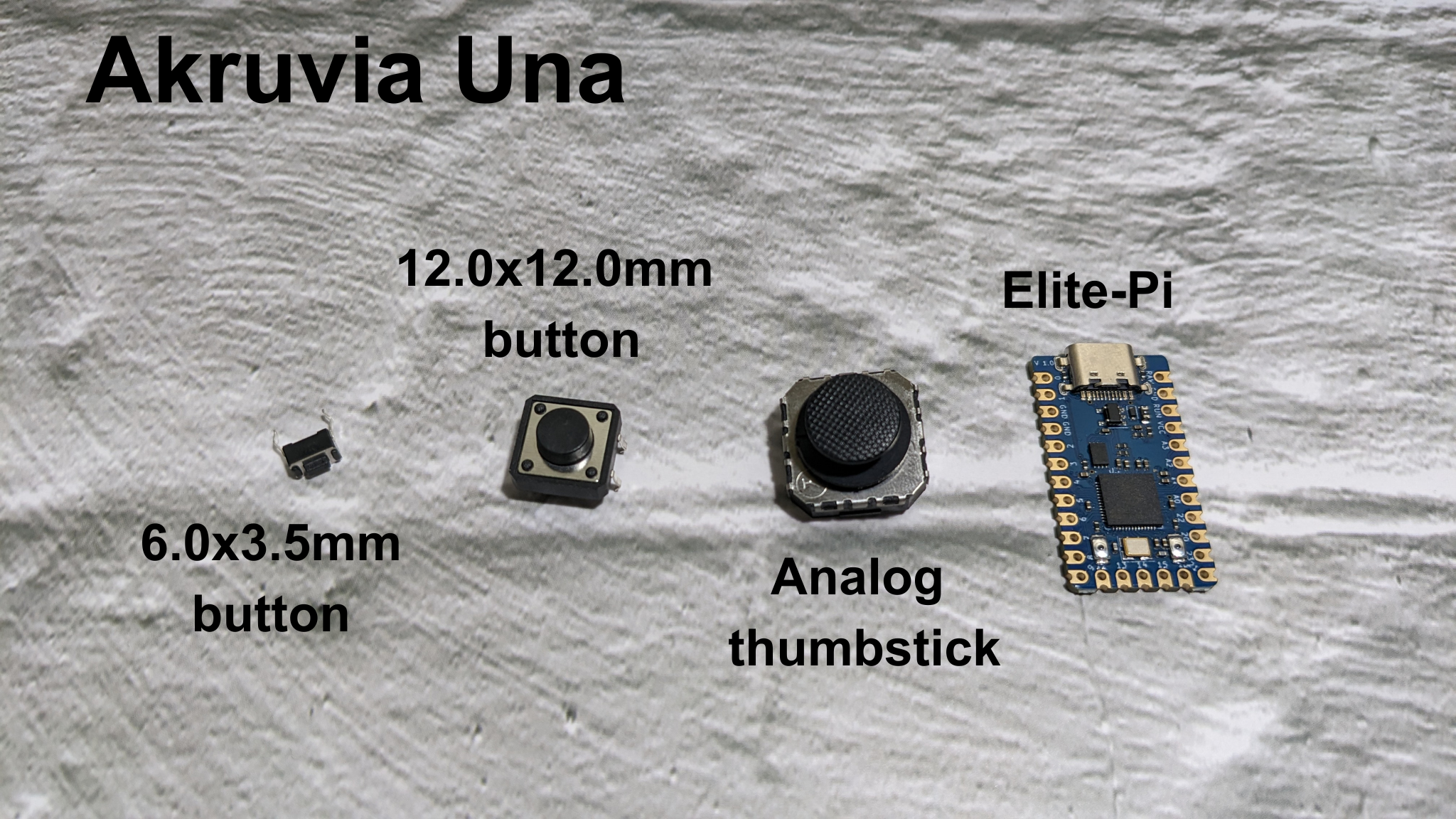
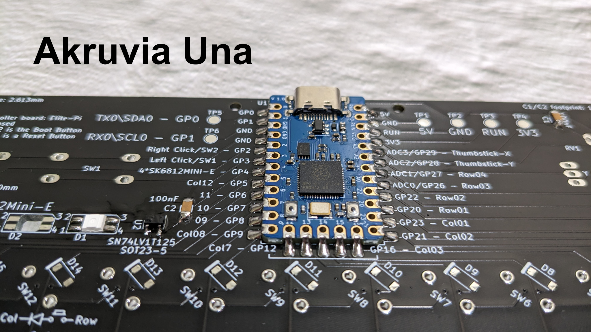
1x Elite-Pi (Ideally flashed with a .uf2 file with an akruvia keymap out of the box)
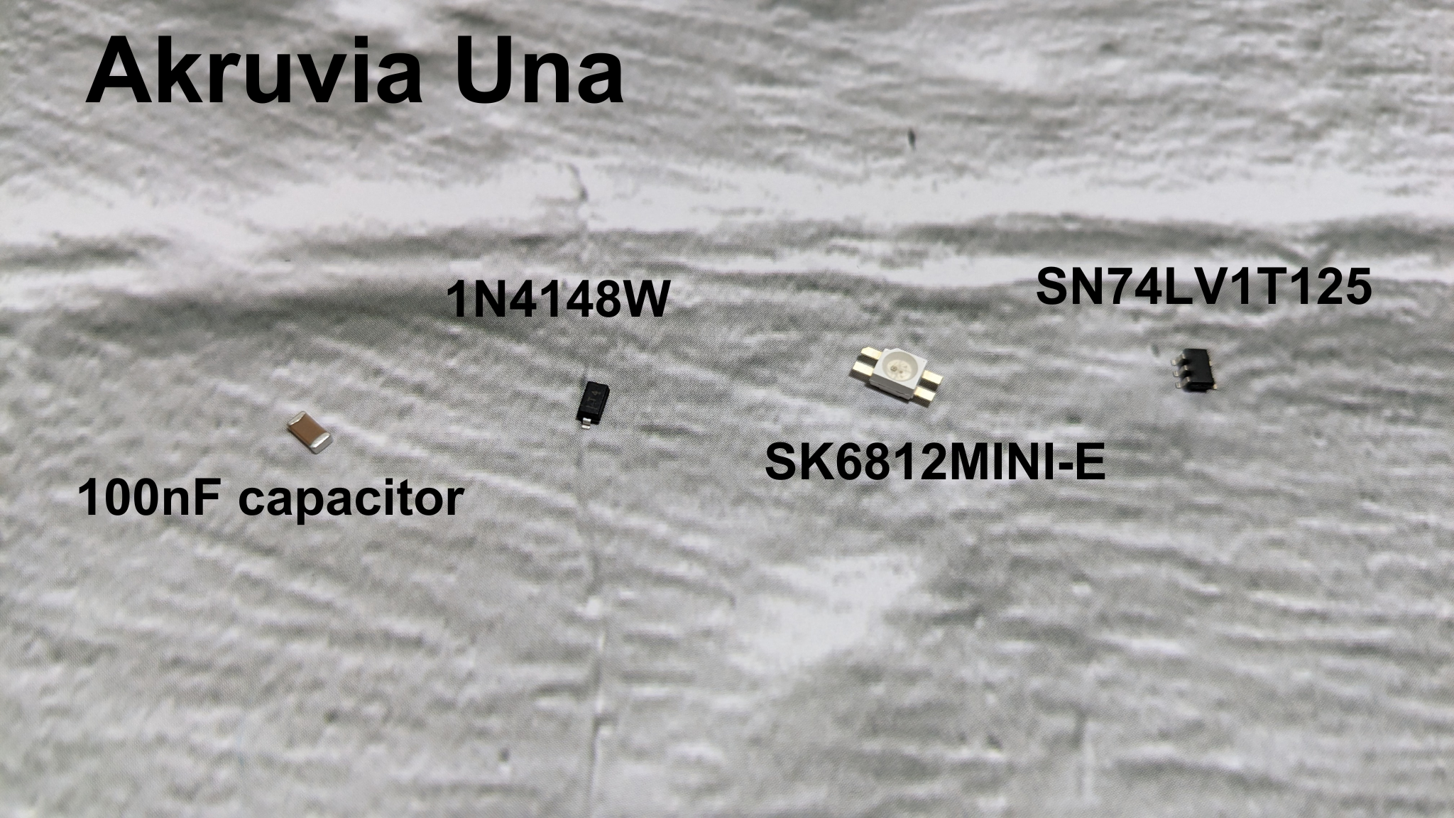
48x 1N4148 diode
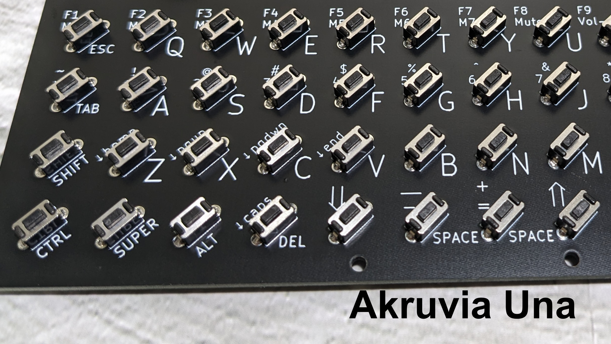
48x 6.0×3.5mm button
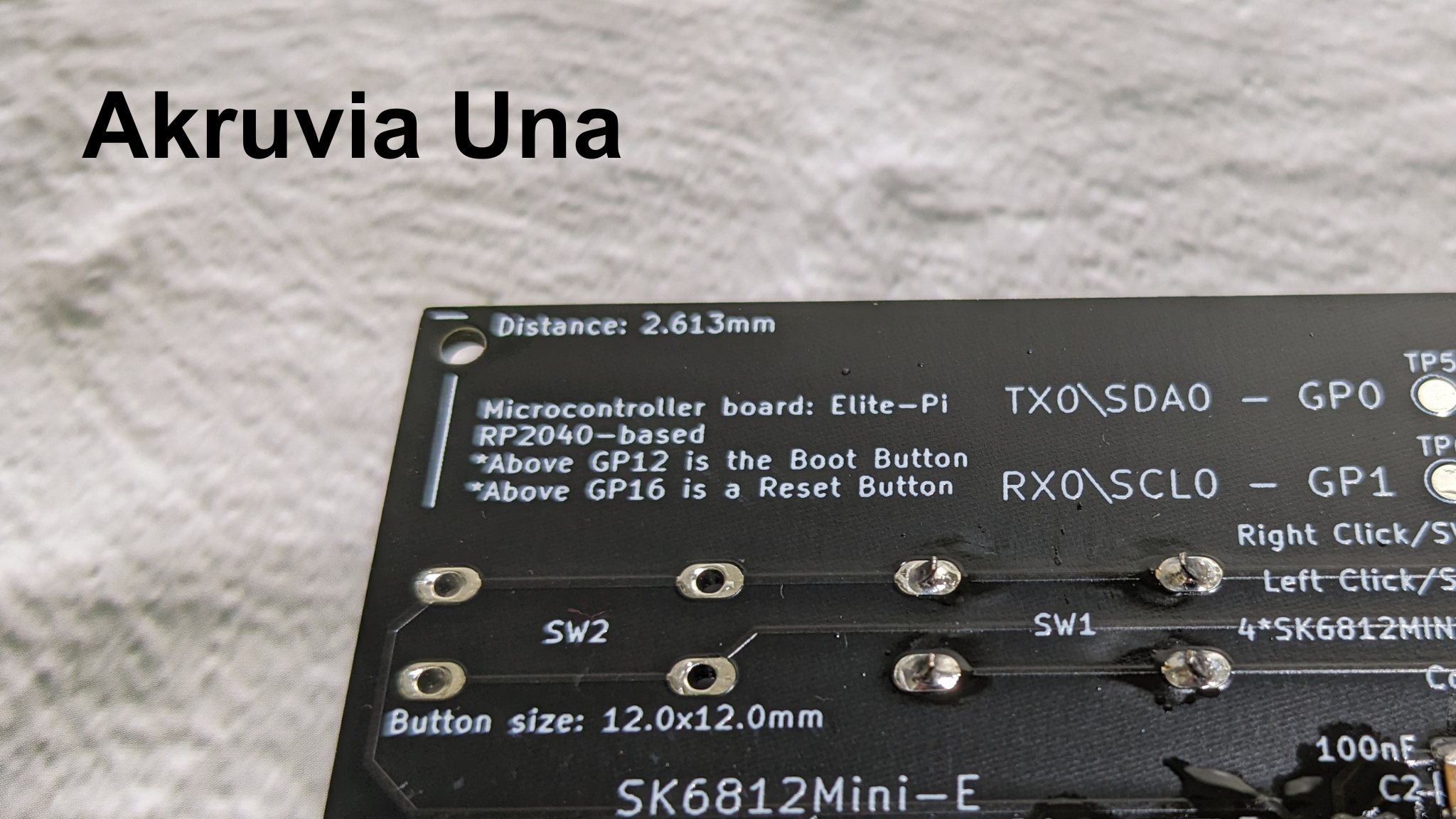
2x 12.0×12.0mm button
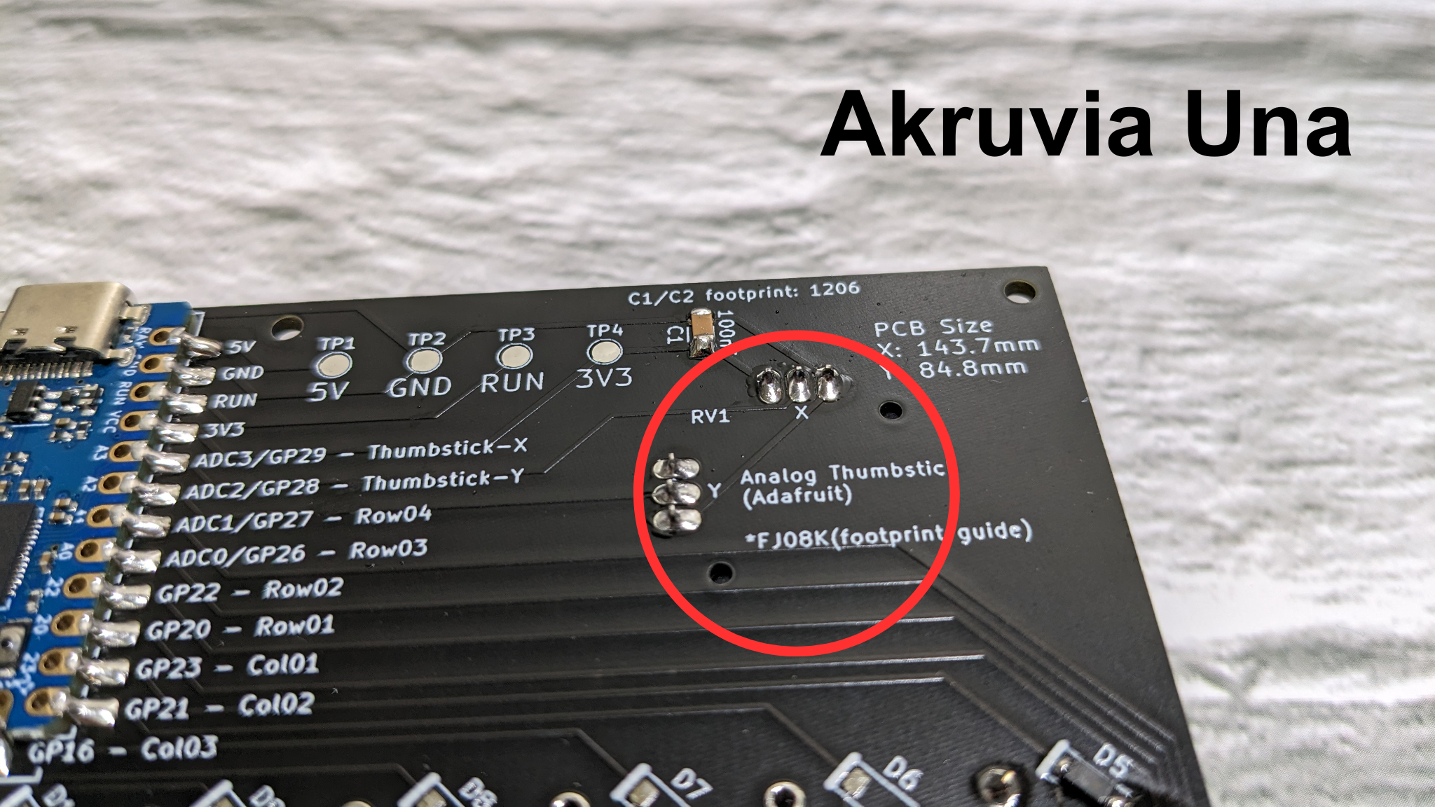
1x Analog Thumbstick
4x SK6812 RGB LED
1x SN74LV1T125
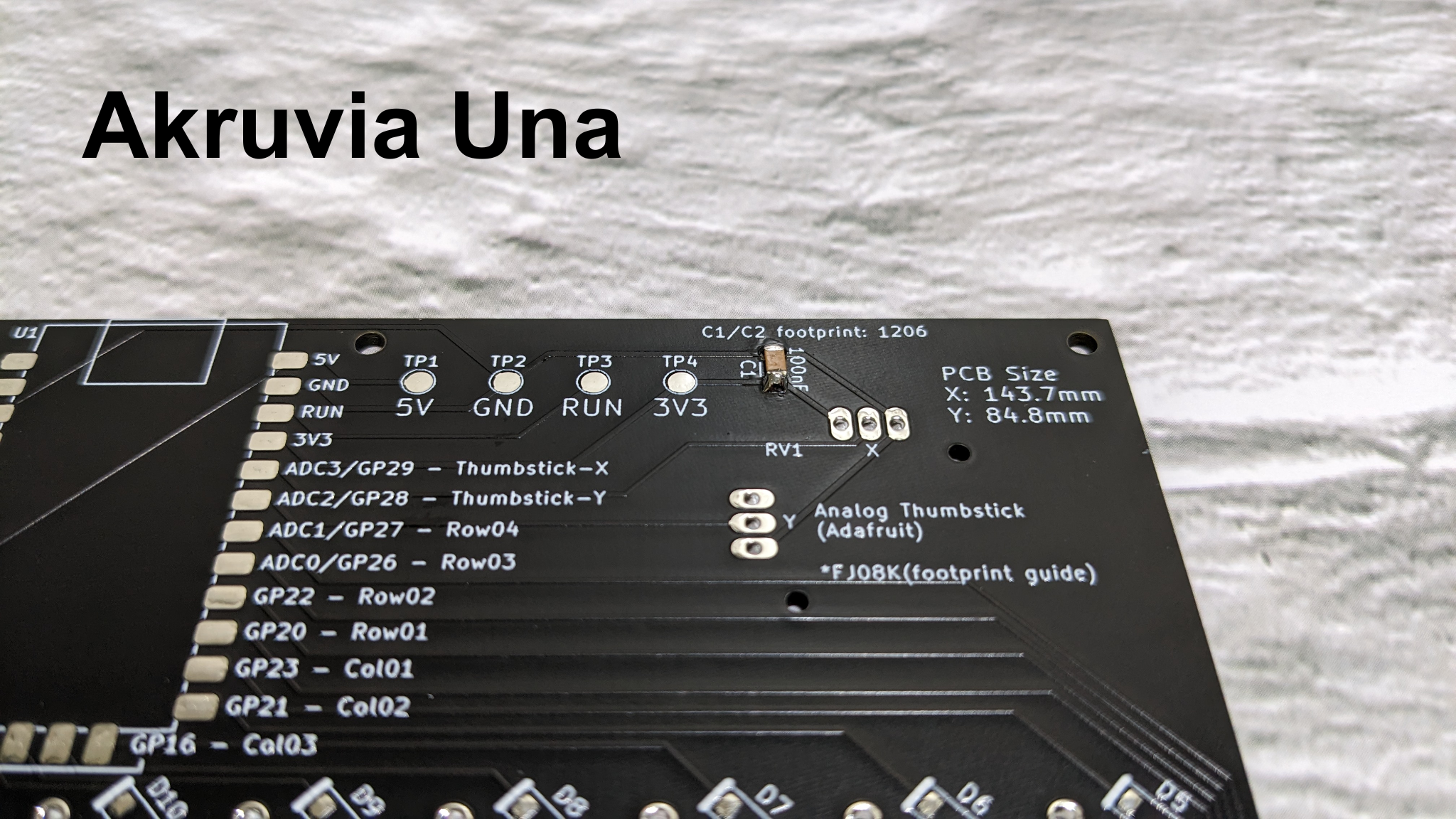
2x 1206 100nF capacitor
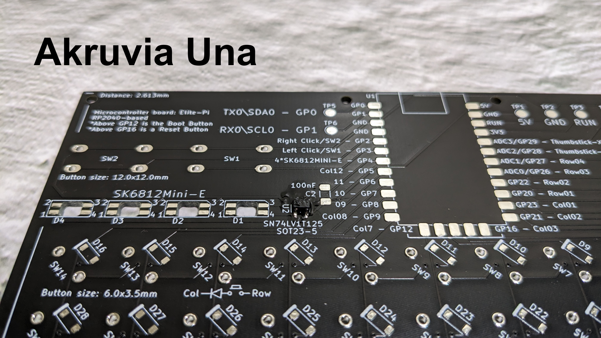
Akruvia Una PCB
There are solder pads for the free GP0 and GP1, 5V, GND, RUN, and 3V3.
GP0 and GP1 can be utilized by editing the code or making your own.


Akruvia Una Components
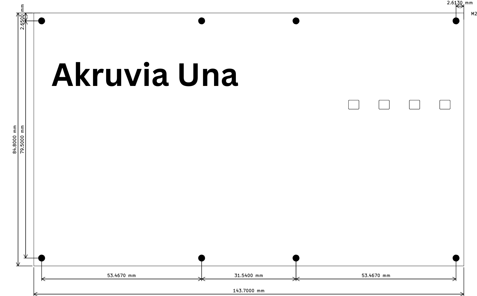
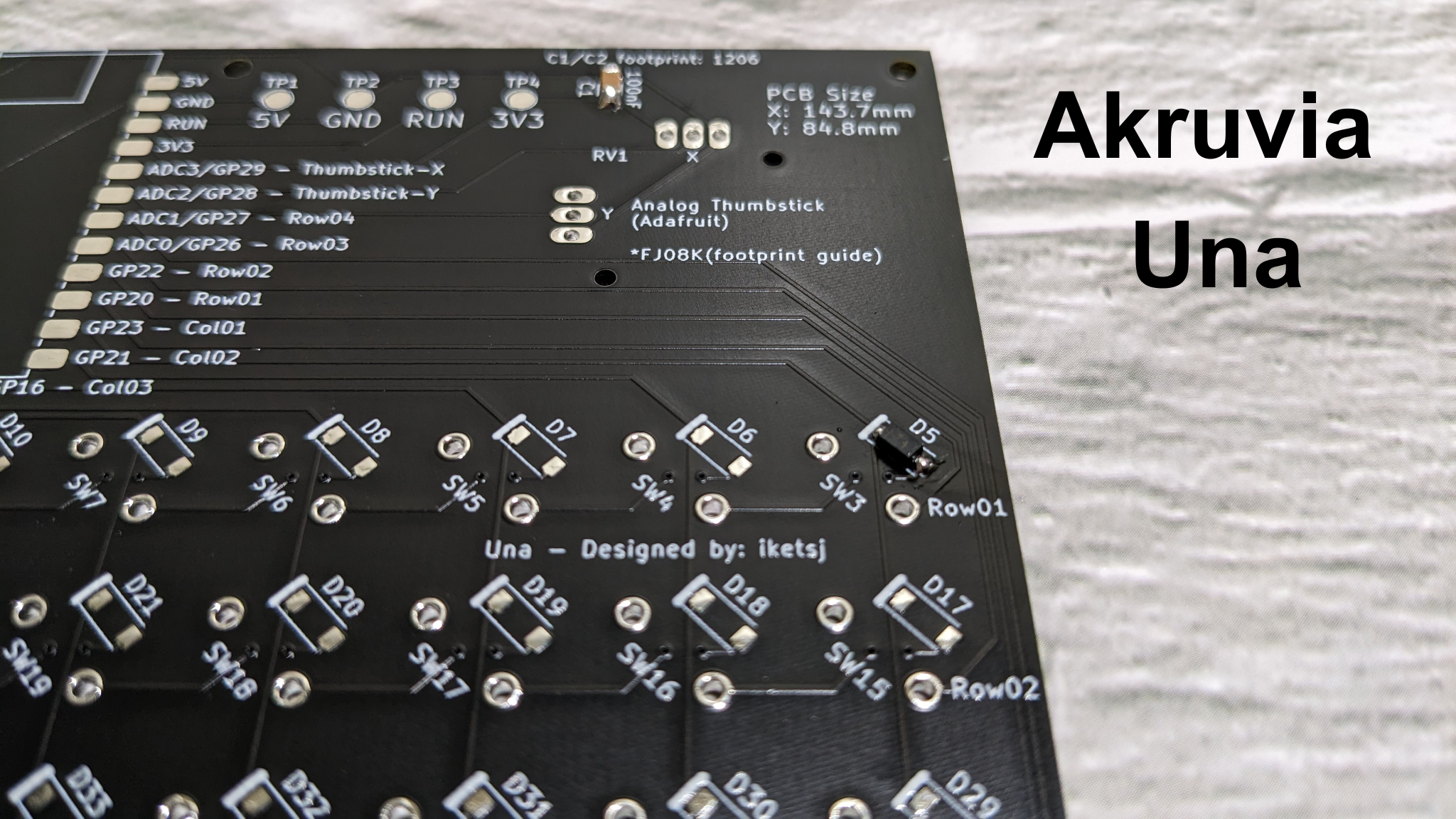
Akruvia Una Dimensions
Assembly Steps:
Step 1:
Solder the SN74LV1T125, it is a one-way logic level shifter. It converts the 3.3v logic from the Elite-Pi to 5V for the SK6812MINI-E to work reliably.
Don’t forget to clean the residue from soldering.
Step 2:
Solder the 2x 100nF caps on C1 and C2.
Step 3:
Solder the 4x SK6812. (From D1 to D4)

Step 4:
Solder the 48x 1N4148. (From D5 to D52)
Step 5:
Solder the Elite-Pi.

Step 6:
Solder the 48x switches for the keyboard. (From SW3 to SW50)

Step 7:
Solder the 2x switches for the mouse. (From SW1 to SW2)
Step 8:
Finally, solder the analog thumbstick.
Flashing the firmware of Akruvia Una on the Elite-Pi
To enter firmware flashing mode, there are 2 ways.
One way is to press the boot button then reset button when a USB cable is connected.
Second way is to hold the boot button right before you connect a USB cable then let go of the boot button.
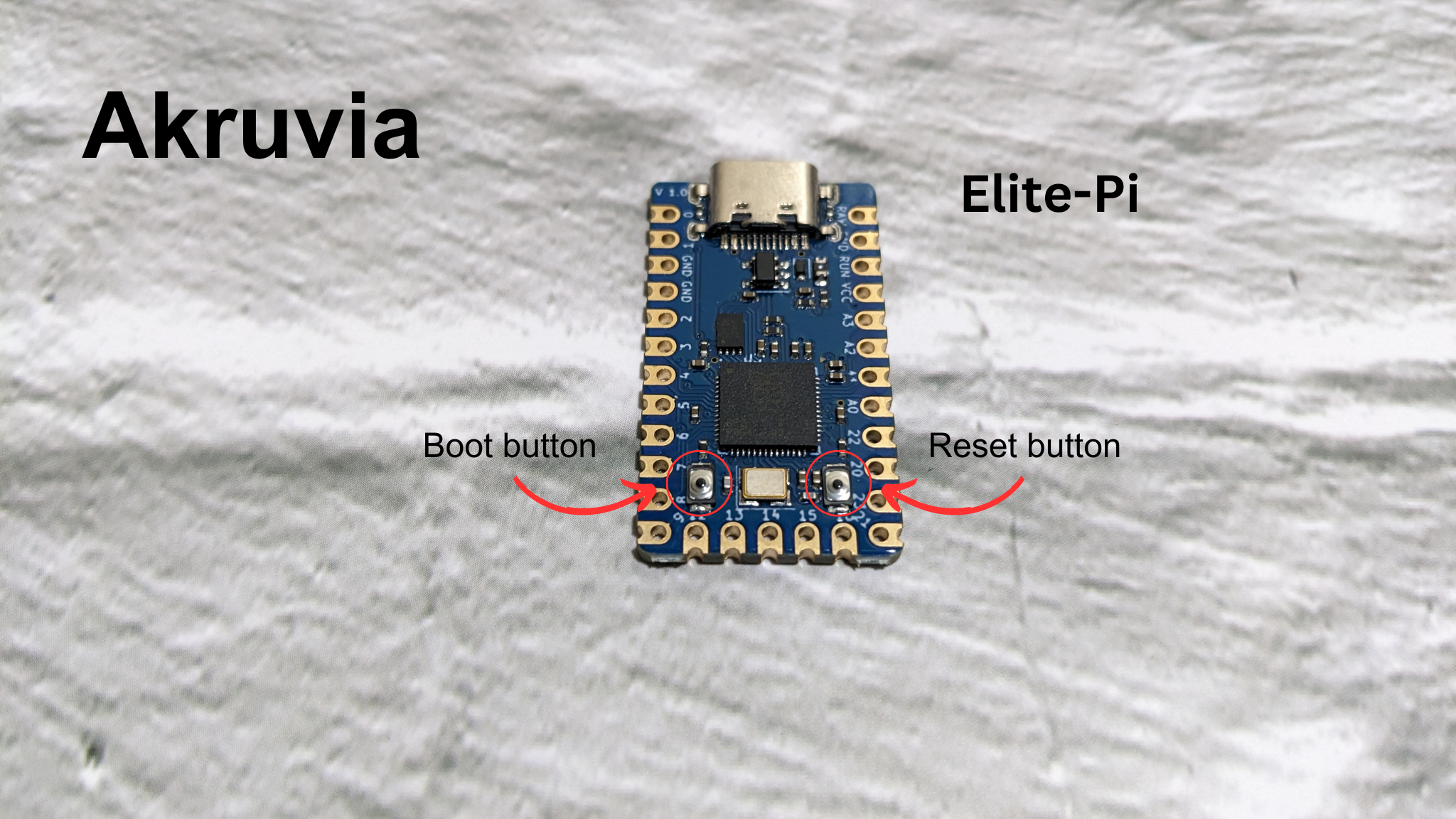
Elite-Pi uses USB Type-C

There would be a device mounted. You can put the UF2 file (.uf2 extension) on this drive for flashing the RP2040. Just copy and paste the UF2 file to this directory or just drag it.
Vanilla firmware is within QMK:
https://github.com/akruvia/qmk_firmware/tree/develop/keyboards/akruvia/una
*You can also write your own code if you want
**within QMK, KMK, Arduino, Pico-sdk or whatever
Building the .uf2 file with the akruvia keymap in QMK:
make akruvia/una:akruvia
-- or build then flash (make sure the board is in bootloader mode) --
make akruvia/una:akruvia:flash
Akruvia Una switch matrix

Akruvia Una Keyboard Layer Behavior (akruvia keymap)
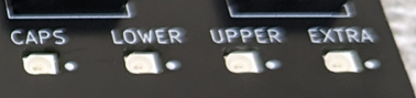
There a 4x RGB LEDs.
For Capslock, LOWER and UPPER for determining current layer, and an Extra RGB LED that is user-assignable by editing the code.
You can technically change the behavior(like the color for example) of any of these LEDs by editing the code or making your own, the legends might not make sense though.
Keyboard layers

Images are made with http://www.keyboard-layout-editor.com/.

Vanilla firmware RGB LED color is red when lit up.

Vanilla firmware RGB LED color is red when lit up.
M1-M7 keys are Macro keys(user-assignable), including the blank keys. The Macro keys just have legends.
You can edit or make your own code.

Vanilla firmware RGB LED color is red when lit up.
The blank keys can be reassigned to whatever you want by editing the code.
Technically, all keys can be reassigned by editing code, but the key legends would not make sense.
Project/s using the Akruvia Una:
Notes:
On the v0.02 of the PCB, the silkscreens for the A2/D28 and A3/D29 for the Thumbstick-X and Thumbstick-Y are interchanged. The X Y silkscreen on the Analog thumbstick should also be interchanged.
There is a default keymap and an akruvia keymap. The default keymap has the default QMK layer toggling(TG) behavior while the akruvia keymap has a custom layer toggling behavior.
Add this to your rules.mk on the Akruvia Una QMK source code for the Caps Lock LED indicator to work properly on Linux-based OS or maybe other OSes:
KEYBOARD_SHARED_EP = yes