
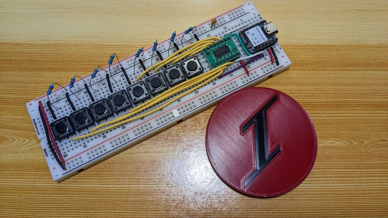
The 74HC165 is an 8-bit parallel-load shift register. We can have this as an option for reading many switches kinda like for mechanical keyboard builds. You can chain many 74HC165.
I just used the native SPI of the XIAO nRF52840 (Sense) to clock-in the read data.
The serial port for this board seems to be crashing often.
The 74HC165 is not a native SPI device but we can use the SPI hardware of the microcontroller to our advantage.

I am going to use SPI Mode 2 so that the sampling is done before the data is shifted.
Data is shifted with low-to-high transition.

Add some capacitor/s on the 3.3v line.
You can tie Serial Input of the 74HC165 to HIGH or LOW when you are not chaining these chips or at the end of the chain.
This Serial Input alongside the Serial Output is used for chaining many of these chips.
Both of the example codes below seems to be identical but they are not.
Way 1 – Wrong behavior
//iketsj
//Code doesn't seem to work because CLK line is getting pulled low
/*
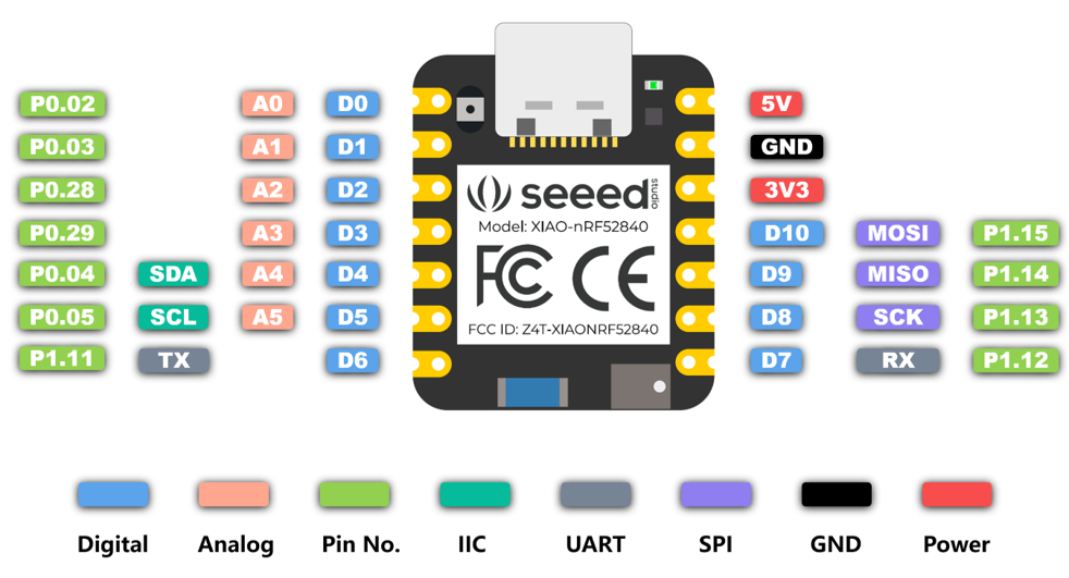
Xiao nRF52840 Sense - 74HC165
D3 - SH/~LD
D8(SCK) - CLK
D9(MISO) - QH
D10(MOSI) - CLK_INH
*/
#include <SPI.h>
#define SHIFT_LOAD 3
#define CLOCK_INHIBIT 10
SPISettings spiSettings(4000000, MSBFIRST, SPI_MODE2);
void setup() {
// put your setup code here, to run once:
Serial.begin(9600);
SPI.begin();
pinMode(SHIFT_LOAD, OUTPUT);
pinMode(CLOCK_INHIBIT, OUTPUT);
digitalWrite(CLOCK_INHIBIT, HIGH);
digitalWrite(SHIFT_LOAD, LOW);
}
void loop() {
// put your main code here, to run repeatedly:
digitalWrite(CLOCK_INHIBIT, LOW);
digitalWrite(SHIFT_LOAD, HIGH);
//CLK is low before beginTransaction
SPI.beginTransaction(spiSettings);
uint8_t valueRead = SPI.transfer(0);
SPI.endTransaction();
//CLK is low
Serial.println(valueRead);
digitalWrite(CLOCK_INHIBIT, HIGH);
digitalWrite(SHIFT_LOAD, LOW);
delay(1000);
}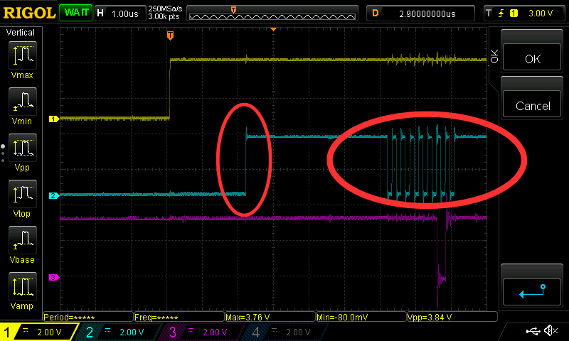
Blue-Green is Clock
Purple is the data shifted.
The clock line is default low in SPI Mode 2 and 3. Then it becomes high when time to clock-in some data.
This is not the behavior we want. We suddenly have 9 low-to-high transitions.

This is due to using SPISettings.
Way 2 – Correct behavior
//iketsj
/*
  Xiao nRF52840 Sense - 74HC165
  D3 - SH/~LD
  D8(SCK) - CLK
  D9(MISO) - QH
  D10(MOSI) - CLK_INH
*/
#include <SPI.h>

#define SHIFT_LOAD 3
#define CLOCK_INHIBIT 10

void setup() {
  // put your setup code here, to run once:
 Serial.begin(9600);
 SPI.begin();
 SPI.setDataMode(SPI_MODE2);
 pinMode(SHIFT_LOAD, OUTPUT);
 pinMode(CLOCK_INHIBIT, OUTPUT);
 digitalWrite(CLOCK_INHIBIT, HIGH);
 digitalWrite(SHIFT_LOAD, LOW);
}

void loop() {
  // put your main code here, to run repeatedly:
  digitalWrite(CLOCK_INHIBIT, LOW);
  digitalWrite(SHIFT_LOAD, HIGH);
  uint8_t valueRead = SPI.transfer(0);
  Serial.println(valueRead);
  digitalWrite(CLOCK_INHIBIT, HIGH);
  digitalWrite(SHIFT_LOAD, LOW);
  delay(1000);
}
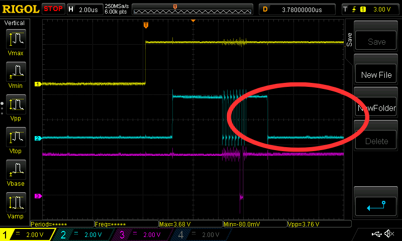
The low-to-high transition count is now 8.
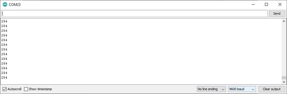
1111 1110 base-2 = 254 base-10
The pressed button is valued 0. Look at the schematic. (Hint: pull-up resistors)
SPI.setDataMode()
is deprecated, but it has the correct behavior for the clock line.
Logic analyzer, Oscilloscope
It is important that we have a logic analyzer and/or an oscilloscope to see what’s going on.
Arduino-based code or not, these tools are invaluable.
Note:
This has no debouncing. Have to implement it.