
Have you experienced seeing a cool costume and hope that you can make one (Yes, we’ve all been there. haha)? Especially with the advent of 3d printing and what not, it is not untypical to see this type of project. I am not saying that the one I made is that cool but at least it is a start.
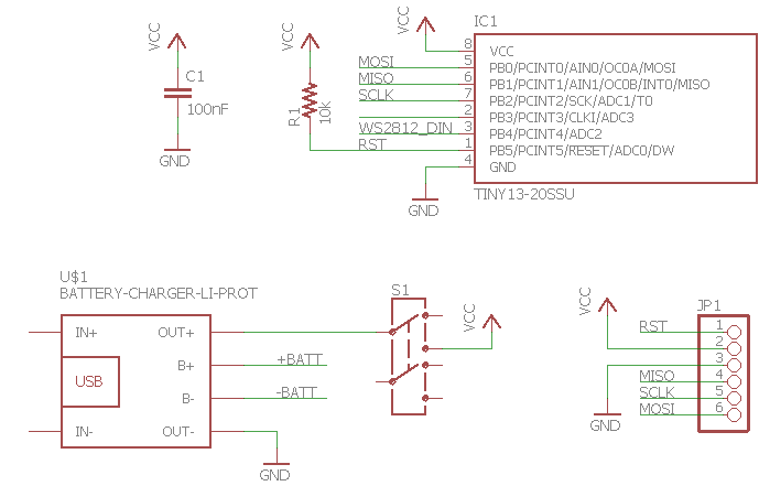
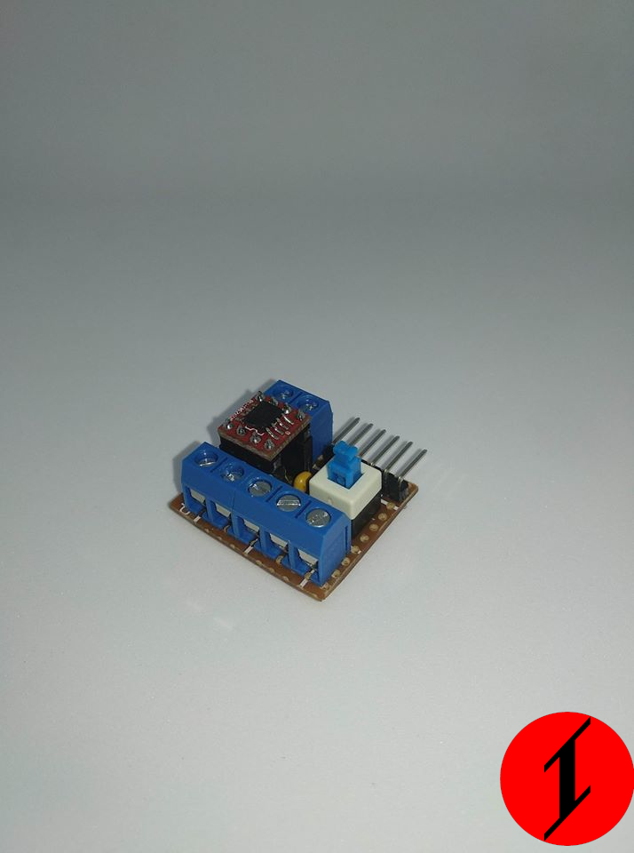
The microcontroller that I used is an ATtiny13A. Its form factor is an SOIC which is not the IC package I planned on buying. Luckily, an SOIC-to-DIP adapter is available at e-Gizmo.
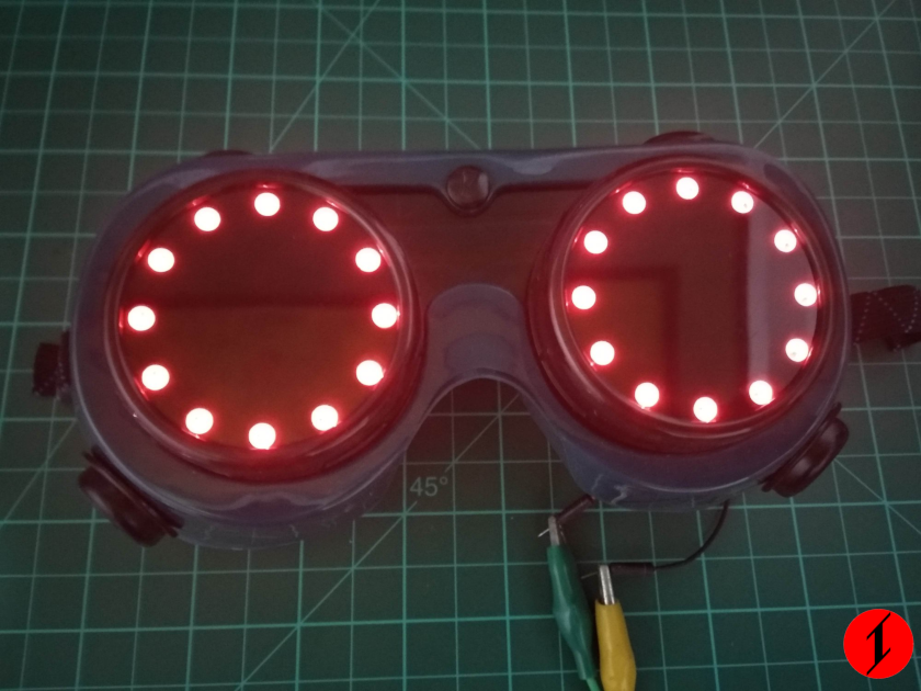
What I did is that I edited a welding goggle that I bought at a local DIY Hardware store. Retrofitting the WS2812 rings were a breeze because they exactly fit on the holder of the optical filter, it is like they were really made for it. I don’t see this exact goggle for sale lately though.


The battery that is used in this project is rechargeable. It is a phone battery which I got from a local CDR-King branch which is now defunct. I added a LiPo charging module to it so that it can be charged easily.

EAGLE is the first electronic design automation software that I learned, so maybe that’s why I am kind of attached to it. It is now owned by Autodesk. Many love and hate it. Anyway, the version of it that I used to create the schematic of the project is version 7.7.0
Now for the coding part, I wrote the code in Atmel Studio but it might as well be called Microchip Studio. But the funny thing is that I actually use a PICkit2 (Not really, but a derivative) to program the microcontroller. It is supported by AVRDUDE. There is a graphical front-end for AVRDUDE that makes life easier called AVRDUDESS. For setting the fuse bits, this also helps.
How to use the WS2812 is explained on its datasheet. It is pretty simple, you just send a 0 and 1 by following a specific timing. But I’ve learned that the timing is not that strict, you can read it here. There is a table there that tells the timing constraints. It seems that I met the 0H and 1H requirements that is specified. TLD is okay too. As for the TLL, the pattern will be shown for some milliseconds anyway. The delay in the code is not the exact 0H and 1H as the compiler produces a different timing. For the 0L and 1L, there is no delay function for it but it meets the timing though. Good thing, I have an oscilloscope.

0H 
0L 
1H 
1L
The frequency of the clock used can still be lowered. But the code would be adjusted. I don’t know what is the C compiler producing to make the delay in code not to be exact as what is passed to the delay functions, maybe we can have some compiler optimizations or something. Rewriting this in assembly language might be fun(and painful. But at least we would know what would be really happening.) if we really want control.
If you are interested in seeing the C code, I uploaded it to my GitHub account. Here is a link.
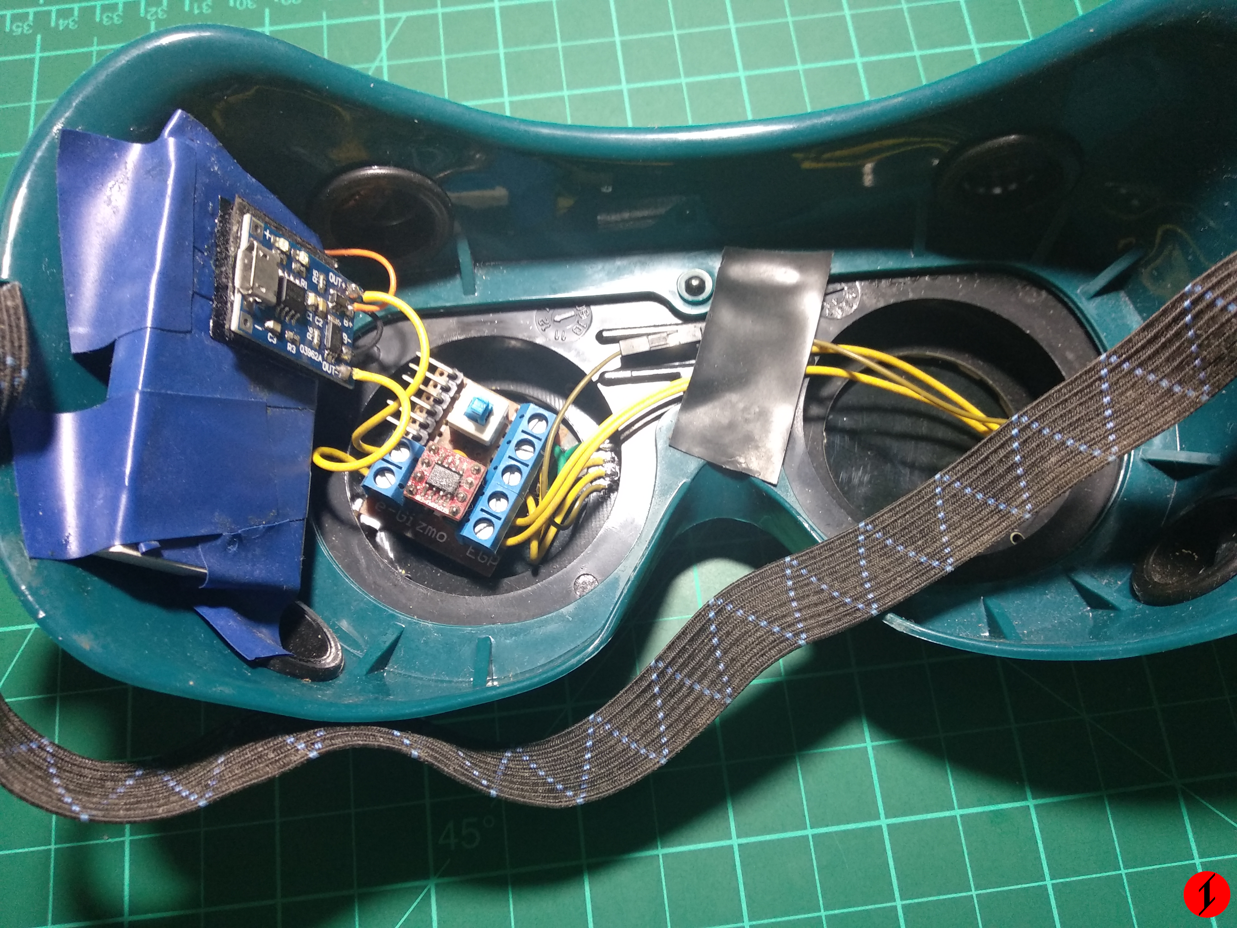
The organization of the wiring can still be improved. Also the way on how things are attached can also be improved.
I wore this goggles to the Manila Mini Maker Faire 2018. The patterns that the goggles can show is not that many but at least it can still attract attention.
I would wear this in events if I think it is suitable. (Note that you wear this over your head, not over your eyes.)