
Buy: Shopee, Etsy
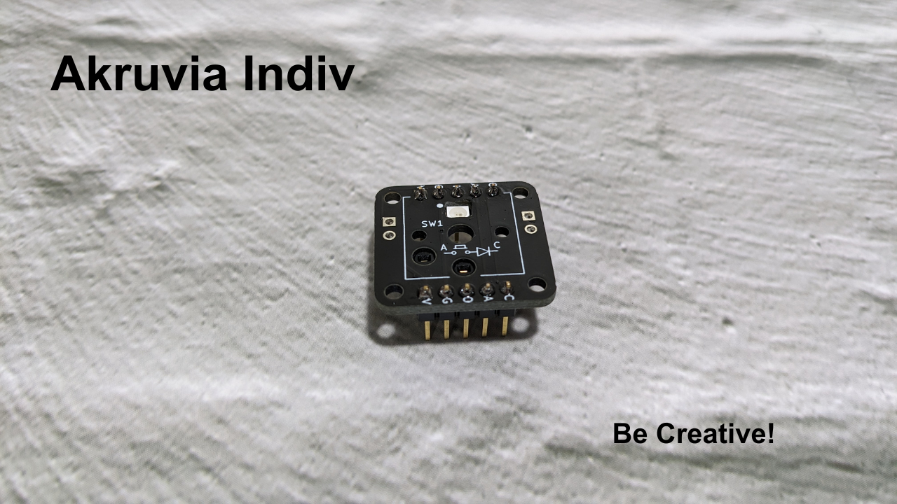
Akruvia Indiv
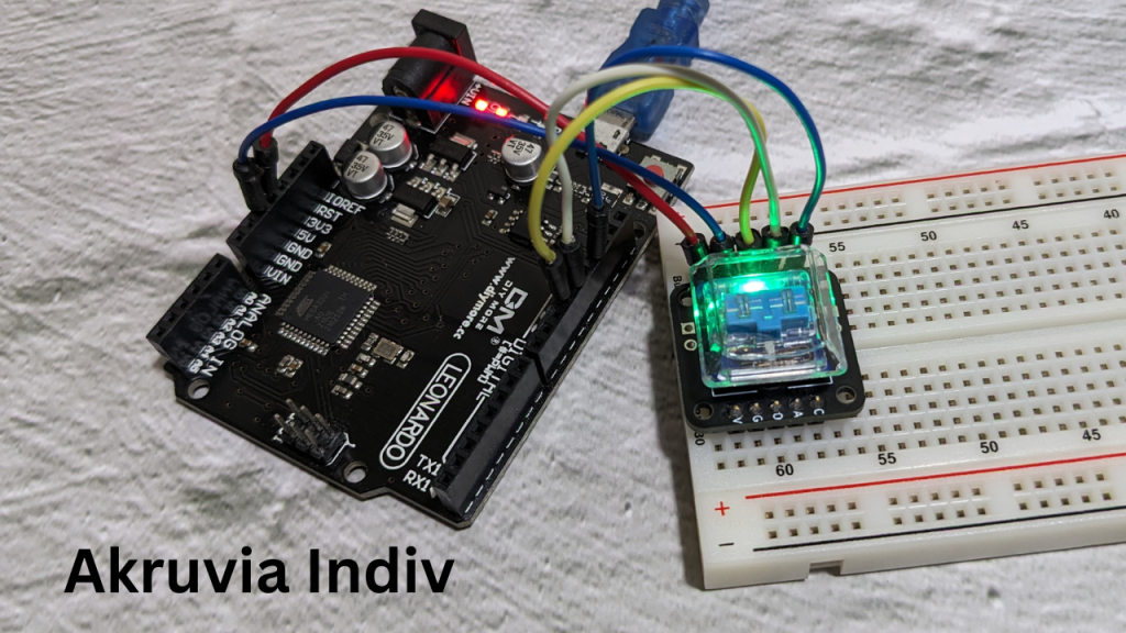
A DIY soldering kit breadboard/protoboard adapter for hot swap Kailh Choc v1 switches.
You can also use this for handwiring a keyboard.
Bring your own Kailh Choc v1 switch and keycap.
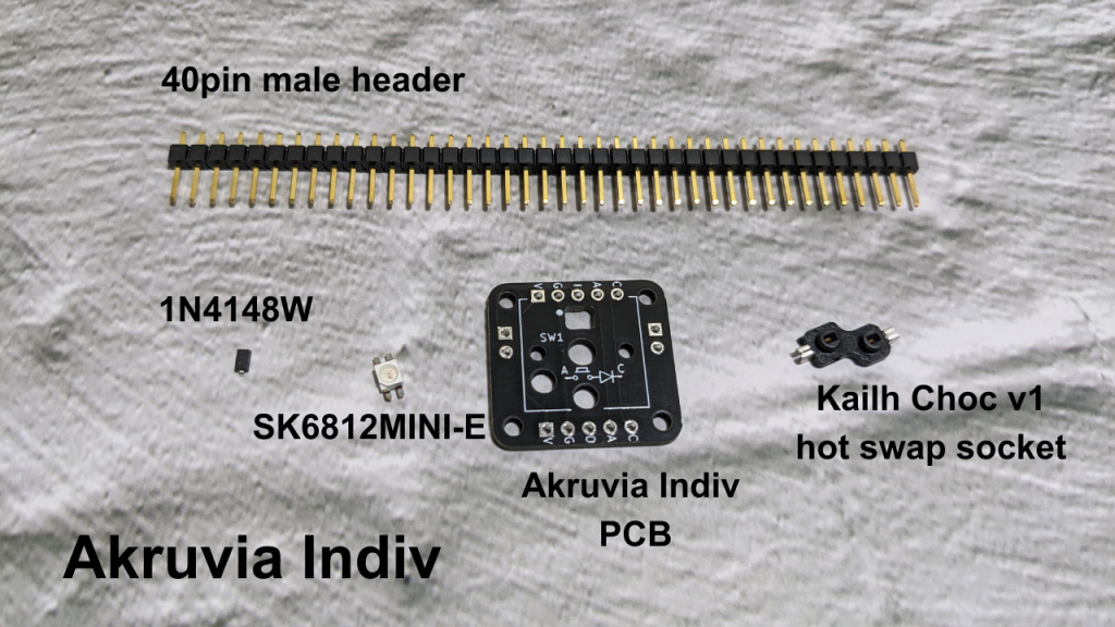
Product inclusions:
1x Akruvia Indiv PCB
1x 1N4148 diode
1x SK6812 RGB LED
1x Kailh Choc(version 1) Hot Swap socket
1x 40pin male header
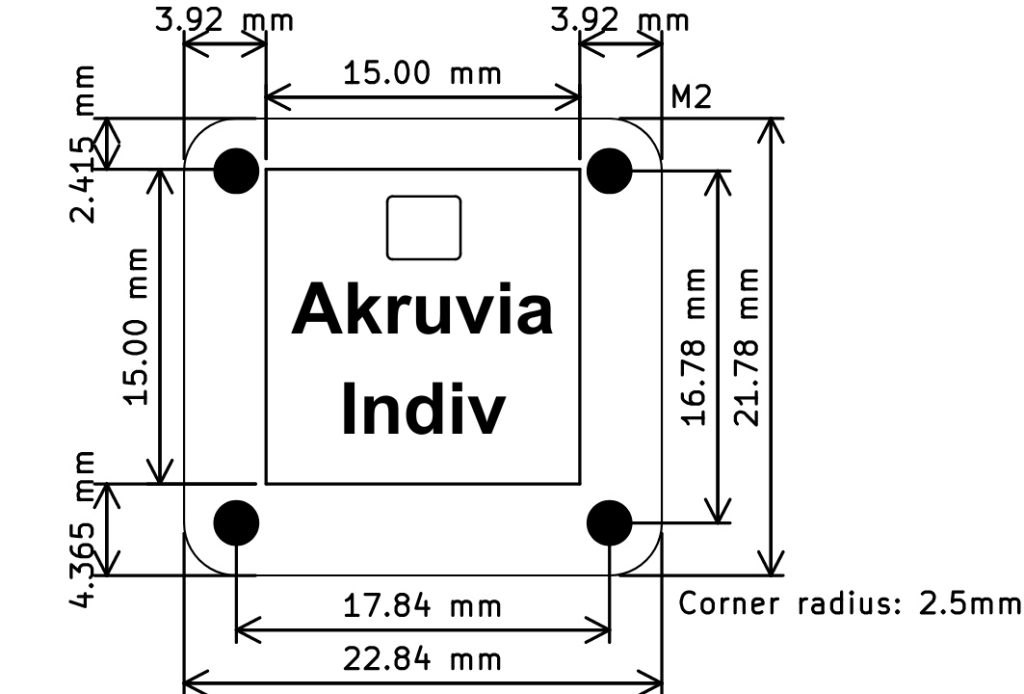
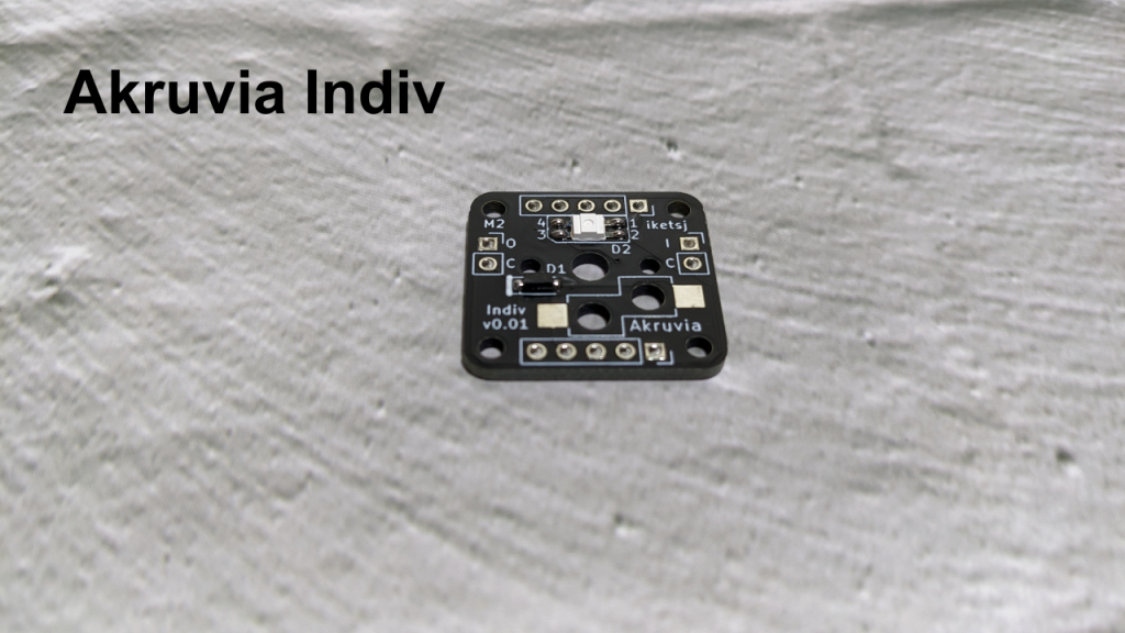
Akruvia Indiv PCB

Akruvia Indiv Dimensions:
ASSEMBLY STEPS:
STEP 1:
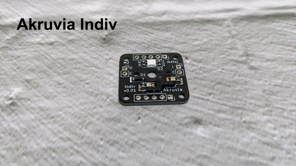
Solder the 1N4148 diode on D1.
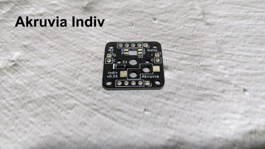
STEP 2:
Solder the SK6812Mini-E on D2.
(If you’re using a 3.3v logic level microcontroller, it is recommended you have a logic level shifter)
STEP 3:
Solder the Kailh Choc v1 hot swap socket.
STEP 4:
Cut 2x 5pin male header from the 1x 40 pin male header.
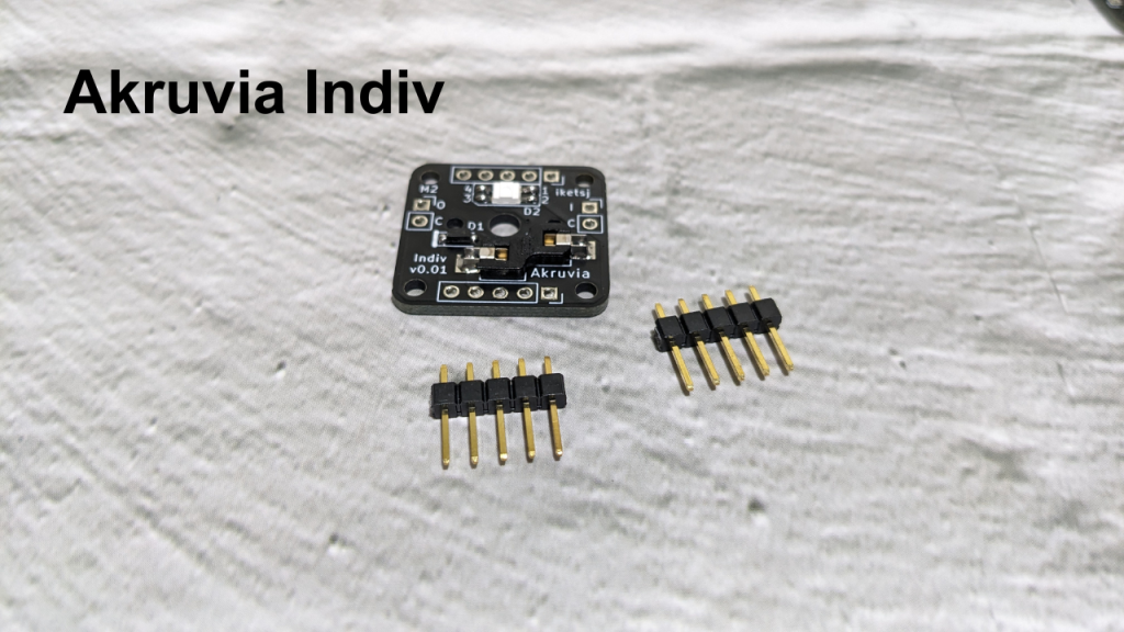
Then solder the 2x 5pin male header.
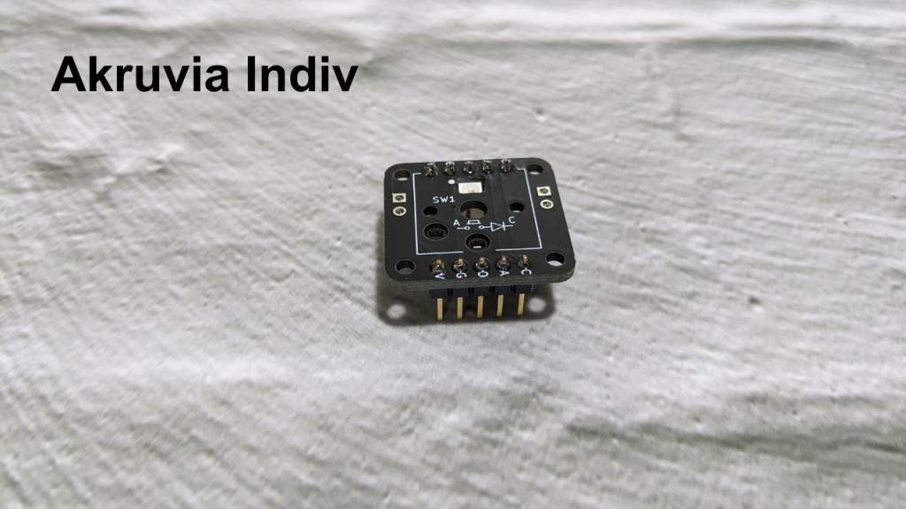
Pinout (Pins with the same label are connected internally):
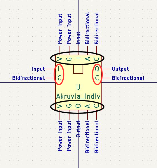
The ones enclosed in red are alternate wiring options.
Pins:
V – Vcc of the SK6812Mini-E (Ideally 5v)
G – Gnd of the SK6812Mini-E
I – DIN of the SK6812Mini-E (Ideally 5v logic level, you can use a logic shifter)
O- DOUT of the SK6812Mini-E
A – the Kailh Choc v1 switch in series on the anode of the 1N4148 diode
C – the cathode of the 1N4148 diode
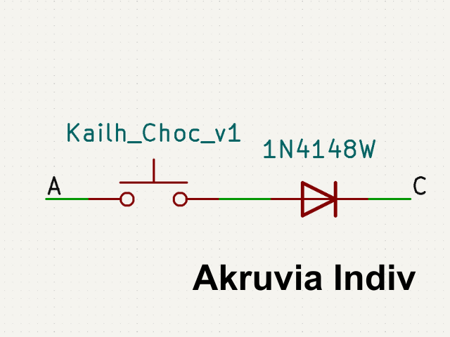
Switch-Diode internal connection:
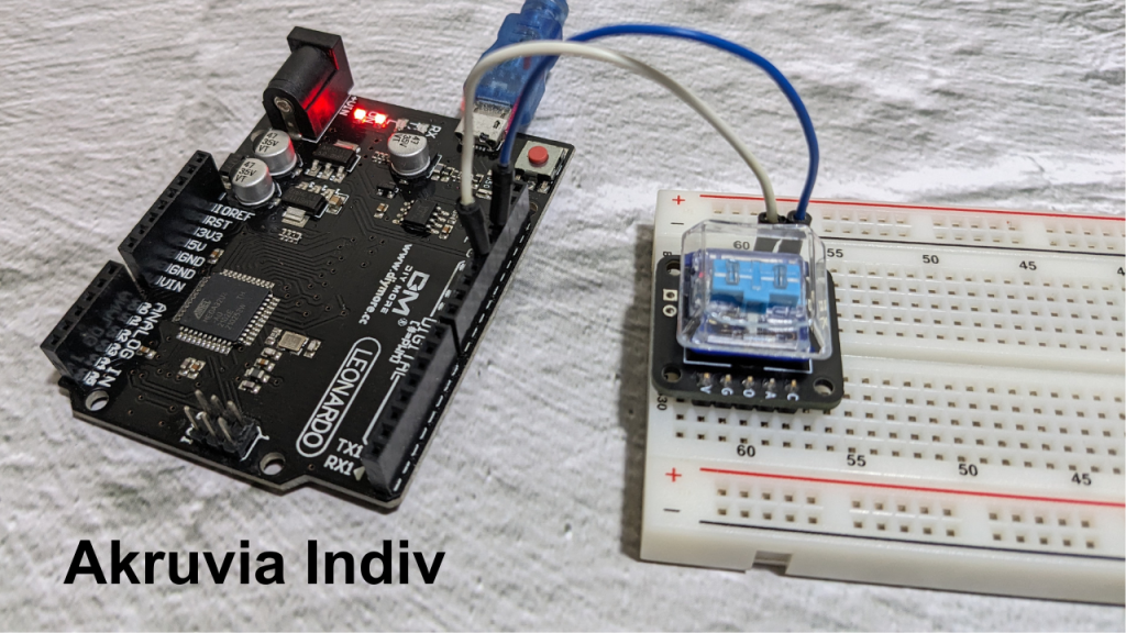
Example Usage:
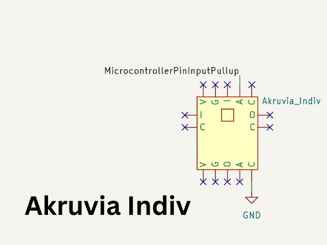
//Arduino example snippet for an Akruvia Indiv direct input connection
//switchPin is the MicrocontrollerPinInputPullup on the illustration
pinMode(switchPin, INPUT_PULLUP);

if(!digitalRead(switchPin)){
	//code here
}
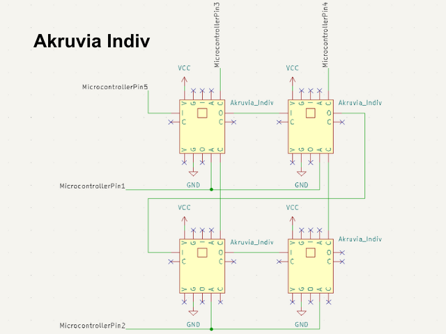
MicrocontrollerPins1-4 are used for button matrix scanning.
MicrocontrollerPin5 is used for the SK6812 RGB LED.
Notes:
- You can use WS2812 libraries with SK6812
- Don’t forget that the pins with the same label is internally connected so you can substitute any connection if they have the same label